





Main Facts: The Ergonomic and Economic Reality of Material Handling
On the modern manual assembly line, the lift-assist device occupies a paradoxical position. It is frequently the last piece of equipment specified during the design phase of a manufacturing cell, yet it is almost universally the first thing operators complain about if it fails to meet the physical demands of the workspace. When a production process requires an operator to lift, rotate, and precisely set a heavy or awkward component into a fixture several hundred times per shift, the material handling mechanism dictates the cell’s overarching ergonomics, cycle time, and overall product quality more than almost any other variable.
Despite this profound impact, the decision of how to equip a workstation often defaults to administrative convenience. Engineers and plant managers frequently select whatever lift-assist device happens to be sitting idle in the facility, retrofitting an ill-fitting tool into a new process. Industry experts emphasize that choosing the right device—and rigorously sizing it to the work at hand—is a critical engineering decision that demands deliberate, calculated planning.
The core variables governing this process are deceptively straightforward: map the work envelope, account for total payload weight (including below-the-hook tooling), evaluate the true duty cycle, and select the smallest, simplest device capable of executing the task reliably. Getting these parameters right transforms a bottlenecked, high-risk assembly station into a streamlined, high-throughput environment.
Chronology: The Evolution of Cell Design and Equipment Integration
To understand why lift-assist specifications are so frequently mishandled, it is helpful to examine the typical chronology of manual assembly cell development.

- Phase 1: Process Conception and Tooling Design. Historically, manufacturing engineers begin by mapping the sequence of operations required to build a product. They focus heavily on the core assembly tools—fastener drives, automated screwdrivers, welding equipment, and custom fixtures. Material handling is treated as an afterthought, assumed to be manageable via standard overhead cranes or brute-force manual labor.
- Phase 2: Cell Layout and Structural Integration. Once the primary machinery is mapped, facility layout planners attempt to shoehorn material handling equipment into the existing architecture. This is where critical errors occur. Because the work envelope has not been thoroughly modeled relative to part pickup and drop-off points, plants frequently install mismatched assets, such as deploying a rigid jib crane where a bridge crane is required, or vice versa.
- Phase 3: Commissioning and Compliance Testing. Prior to full-scale production, the installed system must undergo structural and load verification. According to industry best practices, every unit must be load-tested to 125 percent of its rated capacity and thoroughly documented to Occupational Safety and Health Administration (OSHA) and American Society of Mechanical Engineers (ASME) standards.
- Phase 4: Operational Phase and Operator Feedback. Once the line goes live, the realities of the specification process manifest. If the device was under-engineered, operators quickly experience fatigue, deflection in structural booms, and cycle delays. Conversely, a properly engineered cell achieves seamless integration, maintaining consistent output from the first hour of the shift to the last.
Supporting Data: The Mechanics of Sizing and Ergonomics
Selecting the correct device requires dissecting the physical parameters of the operation. Four primary equipment archetypes cover the vast majority of manual assembly stations, each tailored to distinct operational profiles:
- Fixed Hoist: A hoist mounted to a single, static point. It provides vertical lift at one exact spot and nothing else. It represents the most economical option and is ideal when every lift occurs in a localized zone, such as extracting a machined part straight up out of a vertical lathe.
- Jib Crane: Consists of a horizontal boom that rotates around a vertical mast, with a hoist riding along a trolley. It covers a circular or arc-shaped area. Wall-mounted and freestanding variants offer varying degrees of rotation.
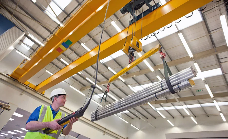
- Bridge Crane: Spans a rectangular footprint, utilizing runways and a movable bridge to service the entire floor area beneath it. This is the premier choice when work is distributed across a wide, grid-like footprint.
- Articulating Arm / Workstation Crane: Advanced pneumatic or electric balancer systems that mimic human arm movements, offering precise, weightless floating of loads with minimal lateral resistance.
Defining the Work Envelope and Reach
Before comparing hardware catalogs, engineers must map the work envelope. This involves identifying three fixed geographical points:
- Where the component arrives.
- Where the work is performed.
- Where the finished assembly leaves.
Sketching these three points alongside the transition path—complete with their respective elevations—defines the three-dimensional volume the lift-assist must cover. Most poor material handling decisions stem from purchasing a device before mapping this envelope. This is how facilities end up with a wall-mounted jib crane whose rotation arc fails to reach an outfeed conveyor, or an expensive bridge crane spanning a footprint that a simple, low-cost jib could have serviced.
Furthermore, reach is not a one-dimensional metric. A jib crane’s boom length sets a radius, but the true working area contains operational gaps. There is an inescapable "dead zone" immediately surrounding the mast where the trolley cannot travel, and any point past the outer tip of the boom is completely inaccessible.

Headroom is another frequently overlooked dimension. The critical metric is hook height—the precise vertical clearance between the component at its maximum elevation and the underside of the support boom or bridge. In facilities with low ceilings, hook height often serves as the binding physical constraint, instantly disqualifying systems that initially appeared viable on a two-dimensional floor plan.
Factoring Total Payload and Duty Cycles
A frequent and costly error in plant engineering is sizing a lift-assist solely to the weight of the raw part. Below-the-hook tooling—including vacuum lifters, mechanical grip jaws, spreader bars, and custom end-effectors—adds significant dead weight to the system. A lift-assist calibrated strictly to the component’s weight will be instantly overloaded the moment custom tooling is attached.
Beyond static weight, lift frequency and duty cycles dictate structural longevity. A station executing five lifts per hour experiences vastly different mechanical stress than one executing sixty lifts per minute, even if the payload mass is identical. Undersized systems manifest this stress through structural deflection, boom flexing, and premature mechanical wear. A flexing boom makes high-precision component placement exceptionally difficult and dramatically shortens the lifecycle of the entire assembly. Sizing the hoist and structural steel to the actual duty cycle—rather than merely the occasional maximum-weight lift—is what guarantees decade-long reliability.
Official Responses and Ergonomic Imperatives
The human cost of poor material handling is well-documented by safety regulators and occupational health organizations. According to federal safety data, overexertion in lifting, lowering, and repositioning loads remains one of the leading causes of nonfatal workplace injuries across industrial sectors. Manual material handling is the primary vector for musculoskeletal disorders (MSDs), which drive the vast majority of lost workdays and workers’ compensation claims in manufacturing.

The National Institute for Occupational Safety and Health (NIOSH) lifting equation establishes an ideal load ceiling of 51 pounds under perfect, laboratory conditions. However, that recommended weight limit plummets rapidly in real-world manufacturing environments that involve reaching outward, lifting from floor level, twisting the torso, or executing repetitive motions—conditions that describe nearly every manual assembly task.
Ergonomic specialists note that well-chosen lift-assist devices fundamentally alter the physics of the job. By neutralizing gravity’s pull on the payload, the operator’s role shifts from lifting heavy loads to merely guiding balanced loads. Aluminum workstation cranes and intelligent balanced hoists maintain push and pull forces well within established ergonomic thresholds across an entire shift. The measurable payoff includes drastically reduced injury rates, mitigated operator fatigue, and consistent throughput from the first hour of a shift to the eighth.
Crucially, ergonomics and throughput are inextricably linked. When a heavy component is fully supported and effortlessly positionable, the lifting phase ceases to be a slow, hazardous, two-person operation. Single-operator handling replaces team lifts, components are seated accurately on the first attempt, and costly rework driven by dropped or misaligned parts is virtually eliminated.
Implications: The Dangers of Overbuying and the Path Forward
A common temptation among plant managers is to over-engineer material handling systems by purchasing the most advanced, high-capacity, multi-axis device on the market "just in case." Industry veterans caution that this approach wastes precious capital and floor space.

The optimal lift-assist is invariably the smallest, simplest device capable of covering the true work envelope at the real duty cycle. A fixed hoist that executes a vertical drop does not need to be replaced by a complex jib; a jib that covers a specific arc does not require a sprawling bridge crane system. Underbuying results in frustrated operators and destroyed equipment, but overbuying ties up capital that could be better deployed elsewhere in the plant.
Structural and Compliance Realities
Underpinning any lift-assist installation are hard structural engineering requirements:
- Freestanding Jibs require deeply engineered concrete foundations to withstand overturning moments.
- Wall- or Column-Mounted Units require verification that existing building steel can safely absorb dynamic operational loads.
- Bridge Cranes demand runway support structures tied directly to building columns or robust freestanding framing.
Furthermore, regulatory compliance cannot be an afterthought. Every newly installed system must be certified, load-tested to 125 percent of its rated capacity, and fully documented to OSHA and ASME standards prior to operational deployment.
Ultimately, a lift-assist device must be conceptualized not as a peripheral accessory, but as an integral structural and functional component of the assembly cell. By starting with the work envelope, rigorously sizing capacity and reach to real-world tasks, and refusing to overbuy, manufacturers can build assembly cells that are safer, faster, and more cost-effective throughout their entire operational lifecycle.