






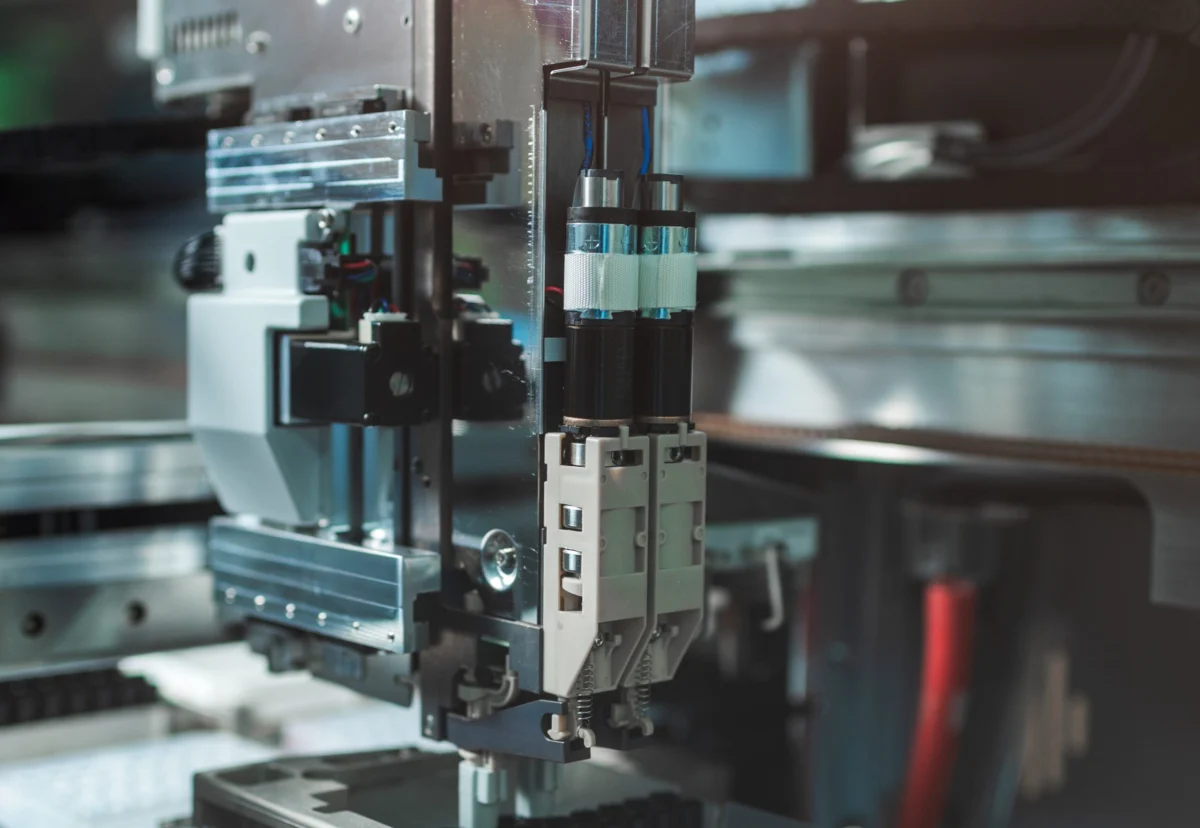
INDUSTRIAL AUTOMATION — In the fast-evolving landscape of modern manufacturing, robotics, and precision machinery, the design of an automated motion system remains a foundational engineering discipline. Whether developing a multi-axis pick-and-place robot for electronics assembly or a custom single-axis mechanism dedicated to a repetitive medical packaging routine, engineers must master the underlying physics, components, and control strategies that dictate machine performance.
This primer explores the essential elements of motion-system design, breaking down the mechanical, electrical, and computational parameters that transform raw electrical power into precise, repeatable physical work.
Main Facts: Deconstructing the Electric-Motor-Driven Ecosystem
At its core, every automated motion system is an electric-motor-driven design built upon an interplay of mechanical actuators and electronic controllers. However, industry terminology often differentiates between two distinct philosophies of machine building:
- Power-Transmission Designs: These machine builds prioritize raw torque, high force delivery, and speed. The mechanical components—such as gearboxes, heavy-duty belts, and robust structural frames—dominate the system architecture.
- Motion Systems: These designs emphasize fine-tuned positioning and precise motion profiles. The engineering focus centers on controlled accelerations, velocity curves, jerk limitation, speed-torque envelopes, and sophisticated homing routines across multiple axes.
Both design methodologies serve as the heartbeat of consumer product manufacturing, office automation equipment, advanced medical devices, and discrete factory automation.
To fully understand where motion systems fit into the broader industrial landscape, engineers must distinguish between discrete factory automation and process automation.
Discrete automation involves working, machining, assembling, testing, capping, wrapping, packaging, labeling, counting, scanning, and transporting individual, separate workpieces. Industries such as automotive manufacturing, electronics production, automated warehousing, and packaging rely heavily on discrete automation, requiring motion systems to precisely place and transport distinct products through multi-step production lines.

Conversely, process automation governs continuous, uninterrupted systems involving fluids, vats of liquids, and chemical batches. These systems manage continuous chemical reactions, temperature controls, and metering operations that cannot easily be started or stopped. Process automation dominates sectors such as mining, energy generation (coal and nuclear), oil and gas, food processing, pharmaceuticals, chemical manufacturing, glass and ceramic production, plastics, textiles, and wood and paper production.
Chronology: The Step-by-Step Motion Design Process
Designing a high-performance motion system requires a structured, chronological engineering workflow. Skipping steps or failing to account for interacting variables early in the design phase invariably leads to operational sluggishness, premature component wear, or catastrophic servo instability.
Phase 1: Quantifying Loads, Friction, and Inertia
The motion design process begins with a rigorous audit of the physical environment. Engineers must meticulously document the loads to be moved, the operational inertias involved, and the static and dynamic friction that the motorized axis must overcome.
Inertia—an object’s inherent resistance to changes in speed—is a critical metric. Total system inertia is the sum of the workpiece load’s inertia combined with the moving parts of the actuation axis.
- Low Inertia: Systems utilizing direct-drive torque motors or linear motors feature minimal inertia because they eliminate intermediate mechanical transmission components.
- High Inertia: Systems incorporating gearsets for speed reduction, belt-and-pulley assemblies, rack-and-pinion drives, chain-and-sprocket sets, or linear screws (leadscrews, ballscrews, and roller screws) exhibit significantly higher inertia reflected back to the motor’s output shaft.
Engineers must calculate how these combined inertias affect the motor shaft. In applications with constantly changing inertia—such as robotic arms executing variable dispensing or machining tasks—advanced motion controls must implement adaptive servotuning to compensate for shifting system dynamics.
Phase 2: Determining Motor Output Force and Torque
Once the mechanical framework, friction coefficients, and total system inertia are quantified, the next step is calculating the required motor output force (for linear motors) or torque (for rotary motors).

Proper motor sizing ensures that the selected electric motor can handle the entire move profile. This includes calculating the peak acceleration torque required to ramp up speed, the constant torque needed during steady-state run phases, and the deceleration torque required to bring the load to a controlled stop.
Phase 3: Selecting Control Architectures (Centralized vs. Decentralized)
With the physical actuators and motors sized, engineers must choose between a centralized control architecture or a decentralized (distributed) drive-based approach.
- Centralized Control: Housed within a single primary electrical cabinet, this traditional approach groups the motion controller, drives, power supplies, and auxiliary electronics together. It offers economies of scale for compact machine installations.
- Decentralized Control: Spreading drives across the machine framework near individual axes reduces long cable runs, mitigates electrical noise and voltage drop, and shrinks the footprint of the main control cabinet. This approach is highly advantageous for large-scale, multi-axis machines.
Phase 4: Integrating Feedback, Safety, and Environmental Hardening
The final developmental phase involves closing the control loop with feedback devices (encoders, resolvers, and sensors), verifying communication protocols, routing shielded cabling to prevent electromagnetic interference (EMI), and ensuring that all components carry the proper IP or NEMA ratings for the operating environment.
Supporting Data & Technical Parameters
To achieve optimal performance, motion system designers must balance several interconnected electrical, mechanical, and computational parameters.
Servo Systems and the Four Quadrants of Operation
High-performance motion systems frequently take the form of closed-loop servosystems. These dynamic machines execute rapid accelerations and decelerations while operating across all four design quadrants—a core industry concept indicating that the control system actively manages the axis across positive and negative values for both torque and speed.
Sizing a servosystem requires a holistic approach that concurrently evaluates:

- Mechanical Parameters: Load mass, lead pitch, gear ratios, and mechanical compliance.
- Electrical Parameters: Continuous Root Mean Square (RMS) current, peak acceleration current, DC bus voltage, and motor winding resistance changes caused by thermal rise.
- Software Parameters: Servo loop gain settings, trajectory planning, and filter tuning.
Motion Profiles and Precision Metrics
At the apex of motion system operation are motion profiles—mathematically defined trajectories commanded by the motion controller. These profiles dictate position commands over time, establishing move times, velocity curves, acceleration phases, and dwell times.
Furthermore, a machine’s practical utility is governed by three critical precision metrics:
- Accuracy: The difference between the commanded position and the actual achieved position.
- Repeatability: The ability of the system to return to the exact same position over multiple consecutive attempts.
- Resolution: The smallest incremental change in position that the system can detect or command.
These metrics dictate the acceptable levels of mechanical backlash and compliance within the transmission components, directly influencing whether the design requires high-resolution optical encoders, magnetic scales, or laser interferometry.
Official Industry Perspectives and Engineering Insights
As industrial automation embraces the Industrial Internet of Things (IIoT) and advanced edge computing, industry experts emphasize the convergence of motion controls and traditional motor drives.
"If we use a zoological analogy to describe automated motion systems, motion controllers serve as the system’s brain—monitoring, commanding, and integrating feedback from every corner of the machine," notes senior automation systems architect Dr. Elena Vance. "Meanwhile, the drives and amplifiers function as the muscular system, translating low-power digital logic into robust electrical currents that conquer physical inertia."
Modern motion controllers run both pre-programmed routines and on-the-fly trajectory adjustments, keeping the error margin between actual and commanded axes positions near zero. According to recent technical briefings from leading motion-control standardization committees, the integration of real-time industrial Ethernet protocols (such as EtherCAT and Profinet) has dramatically reduced jitter, enabling deterministic, multi-axis synchronization down to the nanosecond level.

Implications for the Future of Smart Manufacturing
The rigorous application of foundational motion-system design principles carries profound implications for the future of advanced manufacturing:
- Energy Efficiency: By accurately calculating system inertia and optimizing servomotor sizing, manufacturers can eliminate oversized, energy-wasting motors, significantly reducing plant-wide electrical consumption.
- Higher Throughput and Yield: Advanced motion profiling, coupled with AI-driven vision systems and real-time error compensation, allows automated machinery to operate at unprecedented speeds without sacrificing product quality or increasing scrap rates.
- Enhanced Reliability in Extreme Environments: With robust environmental engineering—including washdown-rated gearboxes, cleanroom-certified linear actuators, and high-temperature shielded cables—modern motion systems can thrive in punishing industrial sectors like aerospace, food processing, and semiconductor fabrication.
By returning to these fundamental design tenets—meticulously balancing loads, understanding inertias, selecting appropriate control architectures, and enforcing strict environmental protections—engineers can build resilient, high-speed automated systems capable of meeting the rigorous demands of Industry 4.0.